
Courtesy of DrifterDon

A little life insurance...
One area the designers of the Drifter didn't address well was the rear lights. The brake light is encased in a small tail light housing and there are no rear running lights other than that tail light and the white licence plate light. Oddly, the front turn signals do double as running lights. I corrected this deficiency with a kit formerly available from Electrical Connection of Knoxville, Tennessee, USA. The kit was advertised to give you bright red running lights in the turn signal housings, a 200 per cent brighter brake light effect and more noticeable turn signals.

EC's kit is solderless and the enclosed diagram - connect the dots - looked simple enough that even I would try it.
Step One in the directions tells you to remove the turn signal bar and unhook the wiring harness under the seat. This is not necessary, at least on a Drifter. You do have to remove the tail light assembly which is held by three bolts inside the fender. The tail light unplugs and you've got a work space. You have to remove the turn signal lenses as well. The kit includes prewired harnesses which are to be jacked into the existing wiring as per the diagram.
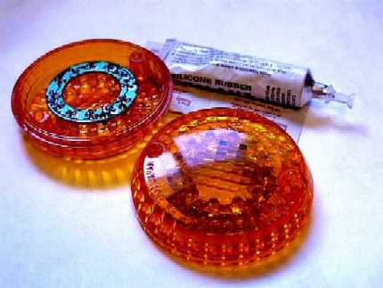
The LEDs are mounted on a circuit board ring which silicons inside the turn signal lens. I did this the night before so I wouldn't lose my nerve and not do the project. The kit also had inline run/brake circuits, so the only actually work was attaching the crimp connectors and guessing which wires to tap into. All connectors are included in the kit; all you need is electrical tape.

Getting back to the turn signal housing, you need some wire to plug the LED ring into. The kit gives you about 30 feet of wire and you need about 10 inches of it for each side. There is no provision for running wire from the housing to the tail light, no holes ets. So the only way is to pull out the brass bulb housing , pull the rubber plug out of the stem,feed the wire through the tunnel and then cram the brass housing back in the hole, queezing the wire against the wall. The wire is thin enough that you can get away with this. The photo above shows the wire in place and the bulb replaced. The bulb will be the turn signals they always were, the LEDs will be bright running lights and brighter brake lights. The square connectors on the wires plug into the LED circuit boards.
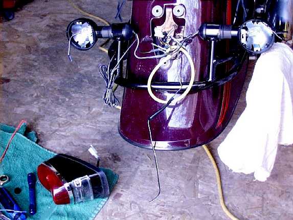

The thick blue and green wires come out of the inline run/brake circuits and clamp into the constantly-on running circuit (tail light) and the intermittently-on brake light circuit with rather clever built in wire taps. The thick red wire comes out the other end of the run/brake circuit and connected to the wire coming from the LEDS. The green kit wires are tapped into the red tail light circuit. The blue kit wires are tapped into the blue brake light (probably a coincidence.) Electrical tape is just extra security to make sure the wire don't pull out when the mess is assembled. The three plug connector is where the tail light assembly plugs in. The grey wore is one of the turn signal wires. The wires from the LEDs tap into that on in a genius piece of technology. The inline circuits in the kit read when the turn signal bulb is on and automatically turns the red LEDs off.
The effect is a flashing red-then-amber turn signal as the bulb and LEDs alternate.

That is quite a bit of wire and stuff to stick under the tail light. Doing this again, I would trim the wires much much more.

At each step of the way, I put the ignition on and tested the running lights, brake lights and turn signals. The lights look yellow in this(and all) pictures because of the brightness of the lights, particularly the LEDs; but all the lights except the bulb-powered turn signals are bright cherry red. With all the circuits hooked up, I taped up the wire to make it neat, plugged in the tail light and bolted it on.
The result is this:

When the bike is rolling down the street, the red LEDS and the tail light are lit. When the brakes are hit, the LEDS in the signal housings light up very brightly. To the eye, the individual LEDs are not actually visible; you just see bright red.

When the turn signals are applied (with or without the brakes) the LEDs go off when the turn signal bulk blinks on.
Three Year Update: Three riding seasons (about 35,000 kms/22,000 mi) later, the unit is still functioning perfectly. I had to re-silicon one of the LED rings to the inside of the tail light lens when the ring came loose. Still very impressed.
Editor Notes:
The PN is 01315. Cost is $49.95.
|
Web site design by Saftek. Copyright © , Saftek Inc. Duplication of any element of this
Not affiliated with Kawasaki. Kawasaki, Vulcan and Drifter are trademarks of Kawasaki. |